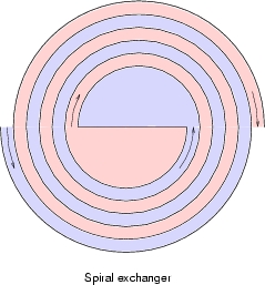
A spiral plate heat exchanger has been modelled. A spiral exchanger essentially is two flat plates wound into a double spiral, with room between them to accommodate fluid flow. They have only one channel per process stream, which to some extent prevents flow maldistribution. They are compact, compared to shell and tube exchangers and do not foul up as easy.
The plate dimensions are: length 8[m], width 0.5[m] and thickness 2[mm]. The plates are Carbon Steel. The distance between the plates is 8[mm]. The width of the flat plate in the center is such, that the total plate length of 8 meters is accommodated in exactly nine complete turns. One channel is a hot water flow and the other a cold water flow. The figure below shows the principle of the arrangement.
The process side is as follows: The hot flow is 8 [kg/s] water of 80 degree Centigrade; the cold flow is also 8 [kg/s] water, but with a temperature of 20 degrees Centigrade. These mass flows are exactly one-fiftieth of the mass flow rate in the flat plate example. The arrangement is counterflow. The initial temperature difference is 60 degree Centigrade. Therefore, it will be interesting to compare the performance of this exchanger to the plate exchanger. To make the comparison of the arrangement easy, the same Adams method is used as for the flat plate exchanger to calculate the heat transfer coefficient (fouling factor of 0.00005 [K.m^2/W]). The total Duty is 769.12 [kW]. When we multiply this with 50, the result is 38.456 [MW], while the flat plate exchanger had a duty of 41.16 [MW]. So, the duty is only 93.4% of 41.16 [MW]. This performance loss is caused by the fact, that the spiral exchanger partially destroys its LMTD as one flow encounters the other flow two times: once at its inner side and once at its outer side. The second time it encouters the other flow, the other flow has completed one turn and thus lost some temperature difference.
Hot water 80 deg C --> 57.03 deg C (55.41 deg C flat plate)In reality, the heat transfer coefficient (and the pressure drop) is higher, due to the curvature of the plates. All in all, the performance will be comparable.
For the physical model, the two passes are divided along its length into 18 subdivisions. The heat transfer area is divided into 36 wall sections, as explained in the flat plate example.
The steady-state solution can be found here. The output allows full cross-referencing of the fluid balances (mass-impulse-energy) whithin the fluid balance model, but also gives full output of the heat conduction model and heat transfer model. Last, but not least, heat flows pertaining to each of these three models can be cross-referenced between the three main models. This makes the heat transfer problem totally transparent.
The approach of AHTL is very flexible. In fact, it would equally
well be possible to model a spiral exchanger with three or four (or any
number of) flows. Vaporizing service is handled correctly by the
generic stream base-model.